A cheap (free) vertical antenna for any band you like.
You will need
- A "Chocolate block" type electrical connector. One piece with three
contacts will be required.
- Un-insulated wire, such as gas-welding rods, stiff copper wire, fence-wire
- Feeder to your rig with the appropriate plug fitted
- Tools - Wire cutters, terminal screwdriver, insulating tape
- A receiver with an S-meter
How to build it
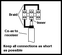
- Prepare the antenna end of your co-axial cable and fit it to the
electrical connector as shown below

Insulate the exposed braid where it crosses the centre of the connector block.
This will prevent it shorting out.
- Cut five lengths of wire 10% longer than the free space 1/4 wave length.
One quarter wavelength = 75/f metres, where f is in megahertz.
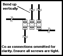
- Fit the lengths of wire to the connector as shown below

- Connect the other end of the feeder to the receiver and tune to a strong
signal near the centre of the band of interest
- Hold the base of the upright section of the antenna. While watching the
S-meter, run your hand up the antenna until you observe a dip in the S-meter
reading. When you are satisfied that you have found the dip, cut the wire off
at this point.
- Measure the upright section and cut the others so that they are the same
length. Measure from the end of the plastic, don't try and judge how far each
connector is recessed into the plastic body.
- Finally, bend the four ground plane sections down at 45º
- The antenna is finished. VSWR will be about 1.3:1. If high transmit power
is to be used, the ends of each section should be filed to a rounded profile.
This will prevent erosion of the ends of the antenna elements which sometimes
happens when you have a sharp point with a high voltage on it.
How (and why) it works
In a quarter-wave antenna, the voltage maximum is at the end. By loading the
antenna (by touching it) we reduce the voltage at that point. Obviously the
greatest effect on received signal strength will occur if we load the point of
maximum voltage on the antenna. Conversely, if we observe the greatest effect on
received signal strength at a given point, it follows that that point must be
the point of maximum voltage on the antenna, i.e. one quarter wavelength along
the antenna.
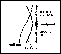
 The drawing on the left shows current and voltage in a half-wave antenna. A
ground plane antenna such as this is effectively a vertical half-wave dipole.
It's radiation pattern is omni-directional. Bending the radials downwards at a
45º angle alters the impedance of the antenna towards 50 ohms.
Summary
This antenna provides a quick and easy way to get a signal out. It is
suitable for all bands, and requires no test equipment other than a receiver
with an S-meter. For 144MHz and up the earth conductor from grey "twin and
earth" household mains wiring makes ideal elements, although the antenna will
require additional support. For the bands below 144MHz, you should consider
using thicker elements to increase efficiency. At lower frequencies you may also
have to fabricate a more substantial connector base.


 The drawing on the left shows current and voltage in a half-wave antenna. A
ground plane antenna such as this is effectively a vertical half-wave dipole.
It's radiation pattern is omni-directional. Bending the radials downwards at a
45º angle alters the impedance of the antenna towards 50 ohms.