When we connect up electrical devices we call the result a circuit. The circuit consists of the components, the supply and the various connection between them. We use standard symbols in our drawing of the circuit, known as a circuit diagram so that it can be easily understood by oithers.
In the example above we have a battery connected to a bulb and a resistor. The current flows out of the battery, through the wire to the bulb. It flows through the filament of the bulb, through the wires and resistor and back to the battery. There must be a continuous path from the positive of the battery, through the bulb and back to the negative side of the battery for current to flow. If this path is broken, no current will flow. This is how a switch works, it simply breaks the path between the two sides of the battery so no current flows.
| A battery and its circuit symbol. The small "pip" on the top is the positive (+) terminal represented by the wider line on he symbol |  |
 |
| A bulb and its circuit symbol. The bulb in the photo is shown in a holder. Screw terminals are provided on the base for connecting wires. | 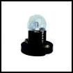 |
 |
| A resistor and its circuit symbol. The coloured bands on the body of the resistor tell us its value. We will learn more about this in the Intermediate Licence course. | 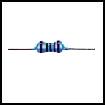 |
 |
The resistor is a device with a specific resistance that limits the current flowing in the circuit. Remember from Ohm's law we dealt with previously, a higher resistance will result in a lower current, so the bulb will glow less brightly if we fit a higher value resistor. A lower value resistor will make the bulb glow more brightly, but if too much current flows the bulb may blow. Resistors are used a lot in electronic circuits to limit voltage and current to specific values.
Some devices, such as the bulb we connected above, do not care which way round they are connected to the battery. This is not true for all devices. Some devices will only function correctly if they are connected to the battery the right way round. This is known as "polarity", and the two battery connections, positive and negative are sometimes known as "poles"
Tutors may like to demonstrate polarity using an LED and battery in a circuit similar to that below.