Section 4 - Transmitters & Receivers
The transmitter and receiver are obviously the heart of the amateur radio
station. In the past it was common for these items to be separate units, but
nowadays most are combined in a single unit known as a transceiver. The use of a
single unit allows many components to be shared, used for both transmitting and
receiving. From the user's point of view, it is an advantage in that there is
only one set of tuning and mode controls to adjust.
 |
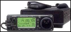 |
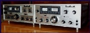
On the left is the Yaesu "F-Line" HF transmitter and receiver
pair c1970, the picture on the right shows a modern Icom IC706 HF/VHF
transceiver. This modern transceiver is about one tenth the size and
weight of a single "F-Line" unit yet covers a greater frequency
range. |
Although the transceiver type of equipment is now the most common, for the
purposes of study we will always deal with the transmitter and receiver parts
separately. For the Foundation Licence we do not need to study the in depth
workings of either, but we must understand the concepts behind their operation.
The drawings used in this section will be the same as those used for all
assessment questions. Candidates are advised to study them carefully and ensure
that they are fully familiar with them.
4.1 and 4.2 The Simple Transmitter
The transmitter is the piece if equipment that generates the radio signal. As
has been said previously, radio waves can travel for immense distances, so the
potential for causing harmful interference is high. For this reason it is
important that we know a bit about how they work.
In order to transmit a signal, we first must make a radio signal at the
required frequency. This is done using a Frequency Generator, also known as an
oscillator. It is important that this device is designed and manufactured with
great care. It must be generating a signal of the correct frequency. If not,
then not only will the person you want to communicate with be unable to hear
you, but you may be causing interference to someone else. It is possible that an
incorrectly functioning frequency generator could cause you to be transmitting a
signal outside the amateur bands. This signal may even prevent someone else's
important radio messages from being heard. Not only would this be a breach of
your amateur radio licence, it could cause significant harm, especially if the
signals with which you are interfering concern safety. It is for this reason
that the Foundation Licence holder is not permitted to design his own
transmitter, but must use commercially available kits or ready-built equipment
which has been "type-approved". Type approval is a process where a
government approved laboratory tests that a product meets the required standards
for use. This testing ensures that such equipment, if used correctly, will
not (unless faulty) cause a signal to be transmitted outside the amateur bands.
The simplest king of transmitter is one where the radio signal is simply
switched on and off with a switch of some kind. Morse code (CW) is sent in this
way. A morse "key" acts as a switch and the signal is switched on and
off to send the information - letters, numbers and punctuation may be sent in
this way. Obviously both the sender and listener must know the code. If we want
to send anything more complicated, such as the human voice, or a picture, then
we need a device to add this information to the radio signal. Such a device is
called a modulator.
These signals we have created are not usually powerful enough to be used for
radio communication, so we must make them more powerful. We do this using an RF
power amplifier. The amplified signals from this device are then sent to the
antenna.
The way in which these devices connect to each other is shown in the drawing
below. This kind of drawing which shows the basic functions of a device is
called a "block diagram". It may also be called a "concept
diagram" since it relates to a functional overview of what is required, not
the actual contents of any specific radio.
 |
!. Audio Stage
2. Modulator
3. Frequency Generator
4. RF Amplifier
|
|
Block diagram of a simple transmitter
|
|
The symbol at the left of the drawing is the standard symbol for a
microphone. Note that the signals coming from a microphone are usually very
small indeed, so we need to amplify them (make them bigger) before we can use
them. This is the function of the Audio Stage.
The symbol on the right of the drawing is the standard symbol for an antenna
(aerial)
|
|
|
|
Microphone
Symbol
|
Antenna
Symbol
|