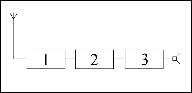
2. Detector
3. Audio Amplifier
Block diagram of a simple receiver
As was stated previously, it is common for the receiver to be part of a combined transmitter-receiver unit called a transceiver. However, many amateurs will also possess one or more good quality receivers. You may use one for monitoring bands other than the one you are working to a assess propagation. Available receivers vary greatly in their complexity and be very cheap or very very expensive depending on performance and features. A basic receiver can be built quite easily and is an ideal first project for home construction.
The function of a receiver is to select the wanted radio signal from the many thousands available and extract from it the data encoded into its carrier. whether that be speech, pictures or data, and pass it to the operator.
The antenna will be connected via the feeder to an RF amplifier to boost the tiny signal it recieves to a useable level. Tuning circuitry selects the wanted signal and rejects the unwanted ones. This circuitry is composed of mostly capacitors and inductors connected to form what are known as "tuned circuits". It is this area of the receiver's circuitry that contains the tuning controls. Commonly, in older manually tuned receivers, a variable capacitor will form the tuning control, but in the case of more modern electronically tuned radios, this will be done by more complex integrated circuits (chips). The ability of the tuning circuit to pick up the wanted signal is called "sensitivity" and its ability to reject the unwanted ones is called "selectivity".
From here the wanted signal is passed to a device called a detector. The type of detector used is dependant on the modulation type employed in the original transmission. Often, multiple detectors will be present, the desired one being selected by the user. The function of the detector is to recover the original modulating signal. This will often be audio, but may be data.
The recovered signal, if audio, must be amplified by an audio amplifier before it will be sufficiently large to drive a loudspeaker or headphones. A recovered data signal may also need to be amplified before being passed to a computer or similar device for further processing.
 |
!. RF Amplifier and Tuning
2. Detector 3. Audio Amplifier |
|
Block diagram of a simple receiver |
The symbol at the right of the drawing is the standard symbol for a loudspeaker. Remember the symbol on the left, it is the standard antenna symbol.
|
|
|
|
Loudspeaker |
Headphones |