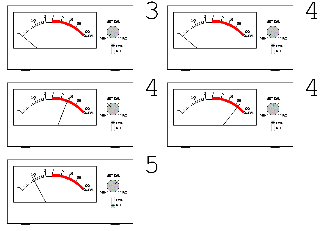
 Single
meter variant
Single
meter variantAs discussed previously, if a mismatch is present between the antenna and the transmitter, then some of the power from the transmitter will be reflected back down the feeder by the antenna. This will combine with the signal travelling towards the antenna and a pattern of stationary waves, called standing waves, will appear to be formed within the feeder.
Two standing waves will appear to be formed, one in the direction from transmitter to antenna, and one in the opposite direction. The size of the standing wave represents the amount of power being reflected by the antenna, and thus it is directly related to the degree of mismatch at the antenna.
A device called a SWR meter is capable of measuring these standing waves as voltages, or currents in the feeder and displaying their size to the operator on one or more meters. The measurement provided by the SWR meter is the ratio of the sizes of these two standing waves, a measure of the degree of mismatch. As low a SWR meter reading as possible is what is desirable. Note that it is correctly called a "Voltage Standing Wave Ratio Meter" or VSWR meter, but the "V" is usually dropped and the term "SWR" used instead.
Measurement of SWR can be taken as a measurement of the quality of the match between our transmitter and our antenna.
There are three main types of SWR meter commonly encountered. Two variants use meters with single needles for indication and must be calibrated as part of the measurement process. he third type is the cross-needle variant. This is most commonly encountered built into an ATU.
 Single
meter variant
Twin meter variant
Cross-needle variant
Note that if you are using an ATU, then except in the case of the cross-needle variant, the SWR meter must be recalibrated after every adjustment of the ATU. In this situation it is normal to just adjust the ATU for a dip in the indicated SWR. When the dip is found, the a calibrated SWR reading is taken to ascertain if further adjustment is required.