It is imperative to ensure that, when amplitude modulation is used, the modulation depth on peaks does not exceed 100% as over-modulation creates serious interference (see Chapter 8)
The actual depth of modulation may be measured by displaying the waveform of the modulated output of the transmitter on an oscilloscope.
The circuit arrangement is shown in Fig 10.5 which is largely self-explanatory. Typical patterns produced are shown in Fig 10.6. By measuring the height R corresponding to a modulation peak. and the height of the unmodulated carrier (S) the depth of modulation can be calculated directly:
![]()

Fig 10.5. Arrangement for measuring modulation depth in which waveform of modulated carrier is displayed. Linear oscilloscope timebase is necessary

Fig 10.6. Typical patterns obtained by method shown in Fig 10.5:

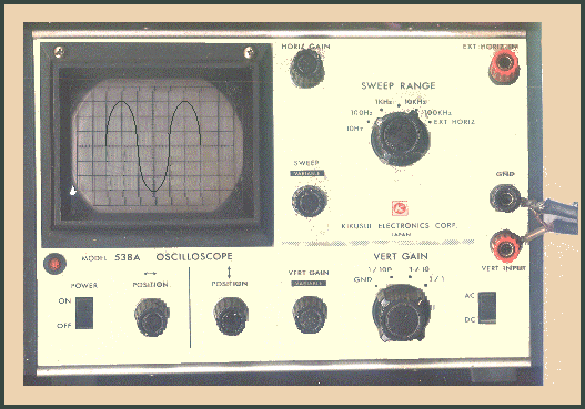
A basic oscilloscope usable only at audio frequencies