This is the case of the large-signal amplifier. Power amplifiers are needed for both AF and RF applications. They are required to provide power to a load such as a loudspeaker or antenna.
The basic circuits will be similar and the operation is the same as the small-signal amplifier but there will be detail differences. There are also variations in order to minimise power dissipation.
The common-emitter amplifier considered earlier provides an exact, but amplified, replica of the input signal - both positive and negative half-cycles of the input are amplified equally. This is defined as 'Class A' operation and can be shown theoretically to have a maximum efficiency of 50%. At low power levels this is not important but if 50W is wanted in the load, then the transistor must dissipate 50W and the power supply has to provide 100W. This would be the ideal case; in practice the amplifier is more likely to be 40-45% efficient. This then represents a high power wastage and of course means the provision of adequate heat sinks. The advantage of Class A operation is low distortion (ie low harmonic content).

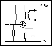
Fig 3.23. Class A amplifier
A Class A power amplifier will look very similar to Fig 3.19. The circuit in Fig 3.23 shows the case when the collector resistor is replaced by a transformer feeding a loudspeaker. This arrangement allows optimum impedance matching.
Efficiency and power wastage are a serious disadvantage of Class A and ways have been found to overcome this. The application will determine the approach. There are two other classes of operation - Class B and Class C.
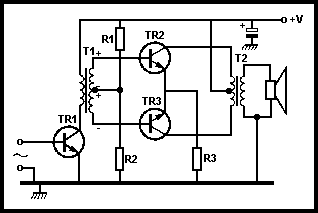
This amplifier only amplifies half a cycle but theoretically it is 78% efficient. In practice it should give at least 66% efficiency. Fig 3.24 shows a typical circuit which as can be seen looks very similar to a Class A amplifier. The difference is that the bias resistors are chosen so that the base is only just at about 0.6V; as stated earlier, if it is taken lower than this the transistor stops passing current. On the positive half-cycle the base current will increase, as does the collector current, and an inverted (but amplified) half-cycle is produced. On the negative half of the input signal, the base is taken to less than 0.6V and so the transistor will not pass current (switches off) and does not amplify. Thus only half of the input signal is amplified. For audio applications a Class B push-pull amplifier is used, as shown in Fig 3.25, while at radio frequencies the collector load is replaced by a tuned circuit.

Fig 3.24. Class B amplifier

Fig 3.25. Class B push-pull circuit amplifier
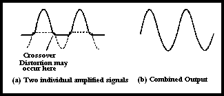
In Fig 3.25 the top transistor amplifies the positive half-cycle and the other the negative half-cycle. They are added together at the output. This is depicted in Fig 3.26. One problem that can occur is that the two halves of the signal do not match exactly due to differences in the transistors, and crossover distortion occurs. To minimise this, some forward bias is applied so that the transistor is passing a small current with no input - this is Class AB operation.

Fig 3.26. Signal combination in a Class B amplifier
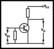
This amplifier amplifies less than half a cycle. A typical circuit is given in Fig 3.27. It will be noticed that there is no bias resistor from base to positive line, only from base to ground.

Fig 3.27. Class C amplifier
The transistor is kept non-conducting by this latter resistor. For the transistor to conduct and hence amplify, the base must be taken from 0 to 0.6V initially (ie part of the half-cycle has already started): the collector current then increases rapidly as the base becomes more positive. As the input decreases the transistor will switch off before the half cycle reaches 0V (ie at 0.6V). On the negative half-cycle of input, the transistor remains firmly in a non-conducting state. The efficiency of this amplifier cannot be quoted exactly as it depends on how much of the half-cycle it conducts for. However, it will be more efficient than a Class A or possibly Class B amplifier - assume about 66%. In a typical Class C transmitter amplifier the collector load is replaced by a tuned circuit. As in the Class B stage, the energy stored in the tuned circuit supplies the other half-cycle.