Valves function by the thermionic emission of electrons from a heated cathode (negative) in a vacuum. The electrons are attracted to an anode which is maintained at a positive potential. Thus electrons flow from the cathode to the anode, but the 'conventional' current is considered to flow in the opposite direction.

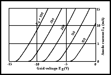
Fig 3.32. Anode current/grid-voltage characteristics
The cathode may be 'directly' heated, in which case it is a tungsten wire which is heated by the passing of a current through it. An 'indirectly' heated cathode consists of a thin tube which is coated with various compounds of barium or thorium and is maintained at the required temperature by a heater which is inside and insulated from the cathode tube.
The basic two-electrode valve or 'diode' is a one-way device, ie it can rectify an alternating current. This application has now been taken over by the solid-state diode.
The addition between the cathode and the anode of a metal grid (control grid g1), maintained at a negative potential, enables the electron current to be changed by varying the voltage applied to the latter. Thus the anode current is controlled. The relationship between anode current (Ia) and grid voltage (Eg) (negative) is shown in Fig 3.32, while Fig 3.33 shows how a valve functions as an amplifier. The anode load is a tuned circuit in an RF amplifier. The similarity to the transistor situation should be noted; it must be emphasized that a valve is a high-impedance device, whereas the transistor is of low impedance.
The terms 'Class A' etc are used to indicate the proportion of the input waveform over which the anode current flows. In Class A anode current flows over the whole of the input wave, and so on. Again the similarity to the transistor situation should be noted.
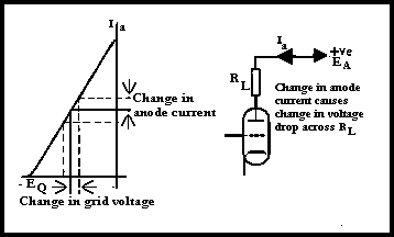
Fig 3.33. How the Triode functions as an amplifier
A second grid, the screen grid (g2) can be located between the control grid and the anode, and such a valve is termed a 'tetrode'. The anode current is now much less dependent on the anode voltage: see Fig 3.34. The amplification and the impedance are increased, but the capacitance between the control grid and the anode is reduced from the order of 5- l0pF to the order of 0.02pF. This is particularly significant because in a triode the higher grid/anode capacitance is in effect connected between the output and the input of the amplifier circuit. Thus there may be sufficient positive feedback to cause oscillation. This capacitance must be 'neutralised' by a small external capacitor. The low capacitance of the tetrode is unlikely to cause oscillation unless the mechanical layout of the circuit is bad.
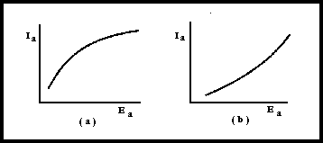
Fig 3.34. Difference between la/Ea, curves of (a) tetrode and (b) triode.
Alternatively the input to an RF amplifier may be applied to the cathode of the valve, with the control grid connected to earth. This is known as 'grounded-grid operation'. The amplification of an SSB waveform must be achieved with the minimum of distortion, hence the requirement for a linear amplifier. This requirement is met by a grounded-grid triode amplifier operating in Class AB. Such an amplifier is also suitable for telegraphy.
Important characteristics of valves are:
While many people think of the thermionic valve as obsolete, they are still the prime choice for high power RF amplifiers. They are cheaper and more tolerant of mismatches than semiconductors. Indeed, almost all the linear amplifiers commercially available for the amateur radio market above 100W output, use valves as the amplifier. They are also still the mainstay of almost all high-power broadcast stations. Perhaps the largest use of thermionic valves today is television tubes. These are basically a large valve, where the electron stream from the cathode is impacted on a phosphor screen to generate light. Modern valves have attained a high degree of reliability, but still suffer from relatively short life at full power compared to their semiconductor counterparts.
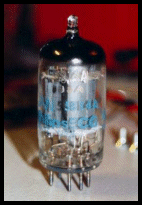

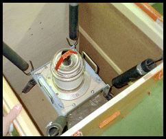
Photo 3.5 Three valves. Left a small receiver type valve. Middle a transmitter valve. Right a high power commercial radio size valve within a 'tea chest' sized packing case.