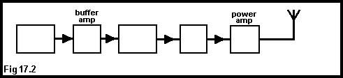
Fig. 17.2 represents the block diagram of a VHF., c.w. transmitter. If X represents the driver, Y the oscillator and Z the frequency multiplier stages, the correct order is
| 1 | 2 | 3 | 4 |
 Back |
| page (tq1701) | |
| Some material Copyright John Bowyer G4KGS. | |
| Click here for important Copyright information | |
| Web Space provided by Hostroute.com Ltd | Contact details |