Section 8 - Operating Practices & Procedures
8.4 Repeaters
What are telephony repeaters for?
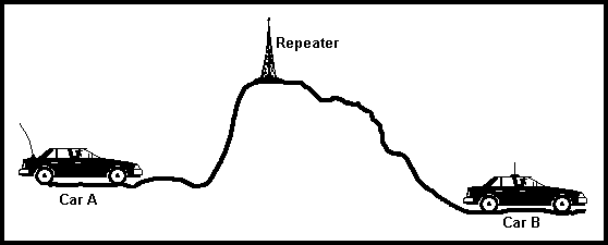
 The
purpose of repeaters is to facilitate usable communications between radio
operators within a given locality operating under circumstances in which normal
communications equipment and methods are inadequate. This is achieved for the
most part by siting the repeater itself in as high a location as possible and
giving it sufficient power to send and receive signals to and from relatively
low powered equipment in the whole of the area it is intended to serve.
Originally the primary purpose of repeaters was to extend the useful range of
mobile transmitters.
Within that area radio operators may move around freely, transmitting their
low powered signals directly to the repeater's input frequency and having them
re-transmitted on it's output frequency, on which the other people involved in
the communication are listening. When an operators transmission has ended he
releases his PTT (push to talk) and his transceiver is automatically re-tuned to
the repeaters output frequency - while the transmitter of the next person to
press his PTT will be automatically switched to the repeater's input frequency.
And so it goes on, with the repeater faithfully re-transmitting on it's
output, all signals detected on it's input, and the users effectively using a
split channel mode of operation - talking on one frequency and listening to the
replies on another. In the UK the usual 2m band split is 600KHz, the repeater
transmits on a frequency 600KHz higher than the input frequency, on 70cm the
split is 1.6MHz.
So how do telephony repeaters really work?
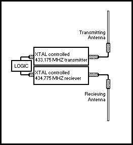
 A
fixed frequency receiver tuned 1600KHz higher than a fixed frequency transmitter
constantly monitors the repeater's input channel.
When a carrier of sufficient amplitude to overcome a pre-set threshold is
detected the incoming audio is passed to a logic circuit designed to detect the
presence of an audio tone of a specific frequency.
Should no such audio tone be detected no further action is taken.
Should a tone be detected however, the transmitter is turned on, and a de-key
timer intended to prohibit re-transmission of accidentally generated signals is
activated. Should the input carrier be dropped before the de-key timer has run
it's full course the timer is reset to it's maximum duration in readiness for
the next over. Should the signal on the input frequency still be present the
de-keyer will activate and close down the transmission automatically.
The tone required to switch on the repeater is normally a 1750Hz tone of
around half a second duration. Some repeaters are now dropping this tone
switching and utilise a system called CTCSS (continuous tone coded squelch
system). In this system, the transmitting station's radio adds a sub-audible
tone to the output signal. When the repeater detects this tone it switches on
its transmitter. The tone is not heard by the receiving stations because it's
frequency is so low as to be inaudible to most people, and the filters in a
receiver's audio stages remove it.
 In
days gone by it was often possible for operators who did not possess
transceivers purposely designed for repeater use to literally
"whistle" at a specific frequency as they keyed the microphone in
order to trigger the audio detector and thus open the repeater. But nowadays
"repeater mode" is a standard feature of all equipment, and in any
case, advances in the use of tone based signals (not necessarily within the
audible range) for other purposes has circumvented this practice on many
repeaters.
That then is a summary of the basic operation and purpose of VHF amateur
radio repeaters. Depending on their location and the needs of the local
community they serve as a focal point in uniting local amateur for nightly
chin-wags or as a means of acquiring valuable traffic information when sited by
a motorway and regularly used by travellers. Of course, amateurs being amateurs,
once a repeater is installed and a long term strategy devised for it's up-keep,
the self-training aspect of it's implementation is complete and other projects
often quickly follow.
The picture on the left shows a typical amateur repeater system. On the left,
the grey 'drainpipes' are the cavity filters which prevent the receiver being
swamped by the signal from the transmitter. Both transmitter and receiver have
to operate at one and the same time and without the careful filtering, the
receiver would not be able to 'hear' your signal on the input. Note much of this
equipment is home made. Construction and operation of repeaters is an entirely
charitable endeavour, often by radio clubs or small groups of amateurs within an
area who see a need for such a facility.
This page based on an article by Colin G6WHL
The original article can be found here http://www.yorkshireatv.org/yt/wy-howto.shtml
 The
purpose of repeaters is to facilitate usable communications between radio
operators within a given locality operating under circumstances in which normal
communications equipment and methods are inadequate. This is achieved for the
most part by siting the repeater itself in as high a location as possible and
giving it sufficient power to send and receive signals to and from relatively
low powered equipment in the whole of the area it is intended to serve.
Originally the primary purpose of repeaters was to extend the useful range of
mobile transmitters.
 A
fixed frequency receiver tuned 1600KHz higher than a fixed frequency transmitter
constantly monitors the repeater's input channel.
 In
days gone by it was often possible for operators who did not possess
transceivers purposely designed for repeater use to literally
"whistle" at a specific frequency as they keyed the microphone in
order to trigger the audio detector and thus open the repeater. But nowadays
"repeater mode" is a standard feature of all equipment, and in any
case, advances in the use of tone based signals (not necessarily within the
audible range) for other purposes has circumvented this practice on many
repeaters.

