Section 8 - Operating Practices & Procedures
8.9 - 8.10 Operating a HF Station
The Transceiver
 For
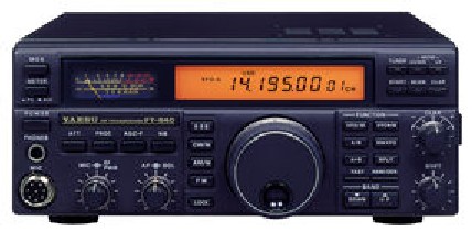
this section we shall consider the Yaesu FT-840 It is an ideal
"entry-level" HF transceiver covering all the amateur bands at a
maximum power output of 100W. It is powered by 13.8V d.c. from a separate power
supply. The transceiver you use will likely be different, but the function of
the basic controls will be the same. Click on the image if you wish to load a
larger picture of this radio.
For
this section we shall consider the Yaesu FT-840 It is an ideal
"entry-level" HF transceiver covering all the amateur bands at a
maximum power output of 100W. It is powered by 13.8V d.c. from a separate power
supply. The transceiver you use will likely be different, but the function of
the basic controls will be the same. Click on the image if you wish to load a
larger picture of this radio.
The Transceiver's Controls
 1.
Variable Frequency Oscillator (VFO) - This is the radio's tuning control; A
large knob is rotated to change frequency. There are also two button to the
lower right of the main tuning knob that allow the user to change to the next
amateur band higher or lower in frequency. The LCD display above the main tuning
knob shows the current operating frequency and mode as well as giving memory
configuration and other information.
1.
Variable Frequency Oscillator (VFO) - This is the radio's tuning control; A
large knob is rotated to change frequency. There are also two button to the
lower right of the main tuning knob that allow the user to change to the next
amateur band higher or lower in frequency. The LCD display above the main tuning
knob shows the current operating frequency and mode as well as giving memory
configuration and other information.
 2.
Mode Selector Switches - This bank of switches selects the operating mode of the
transceiver. Pressing the "SSB" button while already in the SSB mode
will change to the opposite sideband, i.e. LSB to USB or vice versa. Also, when
in the AM or CW modes, pressing that particular button again will switch in an
extra filter (if fitted), changing to a "narrow" mode, shown as CW/N
or AM/N.
2.
Mode Selector Switches - This bank of switches selects the operating mode of the
transceiver. Pressing the "SSB" button while already in the SSB mode
will change to the opposite sideband, i.e. LSB to USB or vice versa. Also, when
in the AM or CW modes, pressing that particular button again will switch in an
extra filter (if fitted), changing to a "narrow" mode, shown as CW/N
or AM/N.
 3.
Mic / RF Pwr - This is a "dual concentric" control, i.e. two controls
on one shaft. A knob at the front adjust the microphone gain, setting the level
of the modulating signal, while a skirt behind it is used to adjust the transmit
carrier power level. Not that when changing operators or microphone, or when
connecting a modulating signal from another device other than a microphone (such
as a TNC) the microphone gain will need to be adjusted to suit the level of the
modulating signal. Failure to do this risks interference being caused by over
driving the modulating circuitry.
3.
Mic / RF Pwr - This is a "dual concentric" control, i.e. two controls
on one shaft. A knob at the front adjust the microphone gain, setting the level
of the modulating signal, while a skirt behind it is used to adjust the transmit
carrier power level. Not that when changing operators or microphone, or when
connecting a modulating signal from another device other than a microphone (such
as a TNC) the microphone gain will need to be adjusted to suit the level of the
modulating signal. Failure to do this risks interference being caused by over
driving the modulating circuitry.
 4.
AF / SQL - Another dual concentric control. The knob at the front adjusts the AF
gain, the volume of the loudspeaker. The skirt adjusts a circuit called squelch.
The squelch circuit switches off the loudspeaker until the level of the received
signal exceeds a certain threshold at which point it switches the loudspeaker on
until the signal again falls below that threshold. The squelch control adjusts
the switching threshold level. Squelch is used to mute the loudspeaker when no
signal is present, its threshold is adjusted so that the operator does not have
to listen to the background electrical noise always present on the HF bands.
4.
AF / SQL - Another dual concentric control. The knob at the front adjusts the AF
gain, the volume of the loudspeaker. The skirt adjusts a circuit called squelch.
The squelch circuit switches off the loudspeaker until the level of the received
signal exceeds a certain threshold at which point it switches the loudspeaker on
until the signal again falls below that threshold. The squelch control adjusts
the switching threshold level. Squelch is used to mute the loudspeaker when no
signal is present, its threshold is adjusted so that the operator does not have
to listen to the background electrical noise always present on the HF bands.
 5.
Shift - More commonly called "IF Shift", this control moves the IF
pass band higher or lower in frequency so that a nearby interfering signal is
outside the pass band but the wanted signal is not.
5.
Shift - More commonly called "IF Shift", this control moves the IF
pass band higher or lower in frequency so that a nearby interfering signal is
outside the pass band but the wanted signal is not.
 6.
Clarifier - Also known as "Receiver Incremental Tuning (RIT)". This
adjusts the tuning of the receiver circuitry while leaving the transmit
frequency unaffected. A station answering your call will often be on slightly
different carrier frequency to you. You should fine tune the received signal
using this control, not the main VFO. If you use the main VFO then the transmit
frequency signal will change also forcing the other station to retune.
6.
Clarifier - Also known as "Receiver Incremental Tuning (RIT)". This
adjusts the tuning of the receiver circuitry while leaving the transmit
frequency unaffected. A station answering your call will often be on slightly
different carrier frequency to you. You should fine tune the received signal
using this control, not the main VFO. If you use the main VFO then the transmit
frequency signal will change also forcing the other station to retune.
 7.
Att - Switchable attenuator reduces all incoming signal levels, usually by a
factor of ten (-10dB). This is often useful in combating interference from very
strong signals.
7.
Att - Switchable attenuator reduces all incoming signal levels, usually by a
factor of ten (-10dB). This is often useful in combating interference from very
strong signals.
 8.
S-meter - Displays output power when transmitting and received signal strength
when receiving.
8.
S-meter - Displays output power when transmitting and received signal strength
when receiving.
The S-Meter
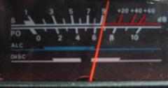 Shown
on the right is a picture of the S-meter of the author's FT-736 VHF/UHF base
station radio. It is similar to that fitted to the FT-840 above, and typical of
many S-meters in that it serves to indicate many things other than received
signal strength. These other functions are selected automatically or by a switch
depending on the mode of operation of the transceiver.
Shown
on the right is a picture of the S-meter of the author's FT-736 VHF/UHF base
station radio. It is similar to that fitted to the FT-840 above, and typical of
many S-meters in that it serves to indicate many things other than received
signal strength. These other functions are selected automatically or by a switch
depending on the mode of operation of the transceiver.
The top scale is marked in 'S' units and displays received signal strength.
It indicates S1 to S9 on the white part of the scale. The red part is marked in
decibels (dB) over S9, +20, +40, and +60dB. The signal strength is reported as
S9 in the case of this signal. If the reading is over S9, then it is usually
reported as S9+, or S9+ and the dB reading on the meter, e.g. S9+20
Making a contact
As part of your assessment you will be required to make an HF SSB contact and
correctly give a signal report to the other station. You will be require to
correctly demonstrate your use of the radio's controls and also the correct
tuning of SSB and Morse code signals.
 For
this section we shall consider the Yaesu FT-840 It is an ideal
"entry-level" HF transceiver covering all the amateur bands at a
maximum power output of 100W. It is powered by 13.8V d.c. from a separate power
supply. The transceiver you use will likely be different, but the function of
the basic controls will be the same. Click on the image if you wish to load a
larger picture of this radio.
For
this section we shall consider the Yaesu FT-840 It is an ideal
"entry-level" HF transceiver covering all the amateur bands at a
maximum power output of 100W. It is powered by 13.8V d.c. from a separate power
supply. The transceiver you use will likely be different, but the function of
the basic controls will be the same. Click on the image if you wish to load a
larger picture of this radio.