'Capacitance' may be defined as the ability of a conductor to store an electric charge. A device in which this effect is enhanced is called a 'capacitor'. In its simplest form, the capacitor consists of two parallel plates as shown in Fig 2.10.

Fig 2.10. Parallel-plate capacitor. The capacitance Is proportional to area A and Inversely proportional to spacing d
The material between the plates is known as the 'dielectric'; in this case the dielectric is air.
The capacitance of such a capacitor is proportional to the area of the plates and inversely proportional to the distance between them. It also depends upon a property of the dielectric known as the 'permittivity' (the dielectric constant). As in the case of permeability, referred to earlier, permittivity is a quantity referred to the vacuum (or air) state. It is hence a ratio or relative property.
Typical relative permittivity are:
| Air | 1 |
| paper | 2 approximately |
| polythene, rubber etc | 2.3 |
| mica | 5 |
| ceramics | 10 and upwards |
The dielectric material determines the maximum frequency at which a capacitor may be used, eg paper up to 20MHz or so, some ceramics and plastics (polythene or polystyrene) up to 150 to 200MHz, and mica even higher.

Photo 2.4. A selection of the more commonly found capacitors.
The capacitor exists in many forms and is classified by the material used as the dielectric. The range of capacitance commonly available is from 1pF to at least 68,000μF. Capacitors have the property of being able to store a charge of electricity and must be capable of withstanding the maximum voltage difference between the plates. Thus the larger the plates and/or the smaller their separation, the greater is the charge that the capacitor holds for a given voltage across its plates. Ultimately, if the voltage between the plates is too high the capacitor will flash over or break down. The safe working voltage is therefore an important property of a capacitor. Capacitors are made with working voltages from 6V to many thousands of volts.
It is clear from its form of construction that a capacitor presents an open circuit to a direct current but it appears to pass an alternating current because of the build-up and decay of charge on one plate and then the other as the direction of flow of the alternating current changes.
Mica capacitors are normally made up to a value of 0.01uF and may be used up to very high frequencies (VHF). They consist of a stack of plates interleaved with layers of mica, which are clamped together, dipped in wax or potted in resin. In the silvered-mica type, the plates are made by spraying a very thin layer of silver on to the mica dielectric. Synthetic materials such as polystyrene, polytetrafluoroethylene (PTFE) and polycarbonate in the form of thin film have now generally replaced paper as a dielectric as their loss as a dielectric is lower than that of the latter. Hence, they can be used at higher frequencies than the normal limit of about 20MHz for paper.
Ceramic capacitors are made by spraying silver 'plates' on to both sides of a ceramic cup, disc or tube. The ceramic used has high permittivity so that a high capacitance is obtained in a small volume. They are made in relatively low working voltages and are most commonly used as bypass capacitors at VHF.
The feed-through capacitor is a form of ceramic capacitor in which one plate is a threaded bush on the outside of a ceramic tube (the 'dielectric'), and the other plate a stiff wire through the centre of the tube. This type is used for feeding through power supplies into a screened box; thus it combines a feed-through insulator with a bypass capacitor.
Electrolytic capacitors have plates of aluminium or tantalum foil with a semi-liquid conducting compound, often in the form of impregnated paper. between them. The dielectric is a very thin insulating layer which is formed by electrolytic action on one of the foils when a DC polarising voltage is applied to the capacitor. As the dielectric is very thin, very high values of capacitance can be put into a small space. The capacitance value can be 68,000μF or more. There is a small leakage current through an electrolytic capacitor and it must be emphasised that generally they are polarised. ie one terminal is positive and the other is negative. Although electrolytic capacitors can withstand a small ripple (alternating) current, this polarity must be strictly observed otherwise the capacitor may explode.
The capacitor has many uses:

The above animation demonstrates the charging of a capacitor through a resistor, after the switch is closed.
There is a small delay, dependant on the value of the resistor and value of the capacitor in attaining a full charge. The higher the value of both, the longer it takes to attain the maximum voltage. Or the larger the bucket (capacitor) and the slower the water flow into it (resistor) the longer it takes to fill. A load across the capacitor (hole in the bucket), would increase the charging time even more.
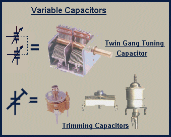
The value of capacitor depends on the size of the plates and on there distance apart. Variable capacitors are ones where the capacitance of the component, by mechanically changing one or the other of the above relationships.

Photo 2.5. The top item is a user adjustable 'tuning capacitor'. The three along the bottom are preset types.
There are two common methods used to vary the capacitance.
a. Two sets of semi circular plates, one fixed, the other movable. As the movable plates are more deeply enmeshed with the fixed ones, the value of capacitance increases.
b. A type where there are two plates, one of which is brought into closer to the other by a screw adjustment.

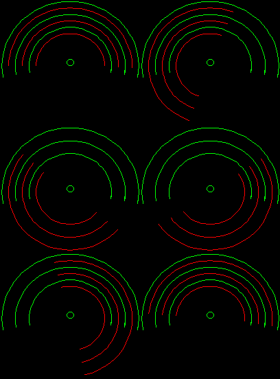
The above animation demonstrates how a variable capacitor operates.
The green semi-circles are the fixed plates, the red ones are attached to the control knob. As the green and red plates become more enmeshed, the value of the capacitance between them rises to the maximum value.
There are two distinct types of variable capacitor, those where the user of the equipment can adjust the value via a front panel control and a preset type which is set during initial manufacture or the later servicing of the equipment.