An inductor consists of a number of turns of wire. However, within the framework of this simple definition there is an extremely wide range of inductance values and types of construction. For example, an inductor required as a tuning coil at VHF might have an inductance of 0.5μH; this would probably be one or two turns of 2mm wire and self-supporting. At the other extreme, a smoothing choke in a power unit would have an inductance of, say, 30H and consist of between 1000 and 2000 turns wound on a paxolin bobbin with a laminated iron core. If this choke were designed to carry a current of 500mA, it might weigh about 6kg and occupy a 15cm cube in volume. Specialist low-frequency applications may require inductance values up to 500H.

Photo 2.2 Two older style chokes, on more modern chokes the windings cannot be seen.


The form of construction depends basically on the inductance value required. The number of turns of wire necessary to give the inductance depends on the permeability of its core. Air has a permeability of 1 but there are magnetic materials which have a very much higher permeability. Hence to achieve a reasonably high inductance without having to wind many thousands of turns of wire on an 'air' core, many fewer turns are wound on a magnetic core appropriate to the particular frequency involved.
The commonest magnetic core is made up of laminations, normally 0.3mm thick of silicon iron. Laminations are available in many shapes and sizes and are insulated on one side so that when they are assembled in a core they are insulated from each other. This reduces the power loss due to eddy currents induced in the core. The commonest shape of lamination is a pair, one being T-shaped and the other U-shaped, so that they fit together when assembled into the paxolin bobbin which carries the winding.
This type of core is standard for low-frequency chokes and power transformers. Thinner laminations of different types of iron are available for use at frequencies in the audio range.
Radio-frequency coils are usually air-cored, either self-supporting or wound on low-loss plastic or ceramic formers. The number of turns involved is often quite small, with inductance values up to about 20μH.
Larger values of inductance up to 1 or 2mH at frequencies from about 100kHz upwards may be wound on dust iron or ferrite cores. A dust iron core is a core of very finely divided iron alloy moulded in an insulating medium. Being moulded, different shapes and sizes can be made cheaply. Often a brass-threaded rod is moulded into a small cylindrical core. The position of the core within the coil can then be adjusted to vary the inductance value to tune the coil to a specific frequency. This is known as 'slug tuning'.

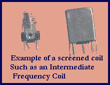
Photo 2.3. A more modern IF-transformer, with its screening can removed (left), and fitted (right).
The modern ferrite cores are non-ferrous materials of high resistivity, and therefore low eddy current loss.
Moulded cores are often in two similar halves as a 'pot' core. The winding is put on a small plastic bobbin which goes inside the two halves and so is surrounded by the ferrite material. Ferrite materials are also moulded in the form of a ring or 'toroid' (a 'toroidal' core). Such cores ensure that the magnetic flux is nearly all contained within the windings, ie there is practically no stray field.