In the AC circuit the voltage and current are not constant with time as in the DC circuit; the value of each alternates between positive and negative states.
The AC waveform is shown in Fig 2.3 and is a 'sine wave' or 'sinusoidal' waveform. There are two values of the amplitude of this waveform which are relevant:

Fig 2.3. Alternation (sinusoidal) waveform
The peak value is clear from Fig 2.3 and the root mean square (RMS) value is that value which is equivalent in heating effect to a DC supply of the same value. For a sine wave, the RMS value is 0.707 times the peak value. The RMS value is used to define an alternating voltage, ie the standard 50Hz supply mains is 240V (RMS) (the peak value is therefore 340V).
The RMS (voltage or current) value of any AC supply is the most commonly quoted value, because these can be directly compared to DC.
Two other values of use are the 'average' value, which is 0.636 times the peak value, and the 'instantaneous' value, which is the value of the current (or voltage) at a particular instant in an alternating cycle. It is usually denoted by small letters, ie i (or v).
The time occupied by one complete cycle is the 'period T' and the number of cycles per second is the 'frequency f.
Thus:
![]()
Phase in this context means 'time' or time difference between two waveforms. For convenience, this time difference or phase difference is measured in degrees; one complete cycle of the waveform is taken to be 360° and a half cycle is 180° etc. Thus the time difference between two alternating waveforms can be defined by the phase angle between them.
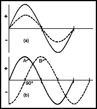
Two alternating waveforms are said to be 'in phase' when they begin at the same point in time: see Fig 2.4(a). At any other point they are 'out of phase'. The term 'in phase opposition' is sometimes used to describe a phase difference of 180°. In this case, two waveforms of equal amplitude would cancel each other.

Fig 2.4.
(a) Two alternating waveforms in phase, ie they start at the same point in time.
(b) Two alternating waveforms with a phase difference of 90o
In Fig 2.4(b), A leads B by 90°, conversely B lags on A by 90°.
Distortion of an alternating waveform is caused by the presence of other sinusoidal waveforms of frequencies which are related to the original frequency (known as the 'fundamental'); thus, if the fundamental frequency is f, then 2f is the 'second harmonic', 3f is the 'third harmonic' and so on.
Fig 2.5 shows the distortion resulting from the addition of 30% of 2nd harmonic to the fundamental (a) and 20% of 3rd harmonic to the fundamental (b). Distortion increases as the number and amplitude of the harmonics present increase. A distorted waveform is often known as a 'complex' waveform.

Fig 2.5. Distortion created by the addition of second harmonic (a) and third harmonic (b) to fundamental
Two new circuit elements are of great significance in the AC circuit. These are:
A circuit possesses inductance if it can store energy in the form of a magnetic field. The unit of inductance is the henry (H) and the symbol for inductance is L . A circuit has an inductance of one henry if a current in it, changing at the rate of one ampere per second, induces an EMF of one volt. The energy stored in an inductor is ½LI2, where L is in henrys and I is in amperes.
A circuit possesses capacitance if it can store energy in the form of an electric field. The unit of capacitance is the farad (F). the symbol for capacitance is C . A circuit has a capacitance of one farad if a charge of one coulomb sets up a voltage of one volt across it. The energy stored in a capacitor is ½CV2, where C is in farads and V is in volts. The farad is an impracticably large unit and the practical unit is the 'microfarad' or μ F (0.000001 farad).
Note that no energy is stored in an inductor if there is no current flowing. In a capacitor, however, there need be no movement of charge and the energy stored is static, A good-quality capacitor can maintain a considerable, perhaps lethal, voltage across its terminals, long after being charged up.
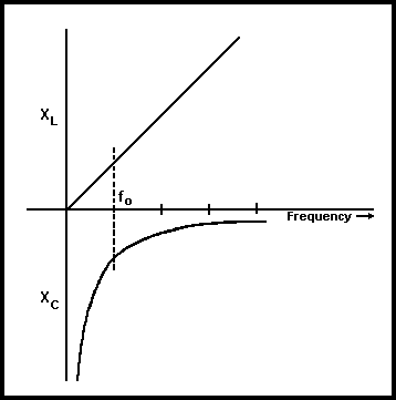
If the effect of resistance is temporarily ignored, the opposition to the flow of an alternating current is the reactance (X).
Inductive reactance XL is the reactance due to an inductance and:
![]()
(π, the Greek letter "PI", is a mathematical constant which may be taken as 22/7 or 3.14 to two decimal places). XL is in ohms when f is in hertz and L in henrys.
Similarly, capacitive reactance XC is the reactance due to a capacitor and:
![]()
XC is in ohms when f is in hertz and C in farads. (Note that 2πf is often written as ω, the greek letter "omega", in mathematical formulae.)

Fig 2.6. How the reactance of a capacitor and an inductor vary with frequency
When an alternating voltage V is applied to a resistance R the current which flows is exactly in step with the voltage. The voltage and current are said to be 'in phase'. The value of the current will be by Ohm's Law:
![]()
When an alternating voltage, V. is applied to an inductor, L , (Fig 2.7) the current which flows will lag behind the voltage, the phase difference being 90o The current flowing is given by:
![]() where XL
is the inductive reactance, 2πfL ohms
where XL
is the inductive reactance, 2πfL ohms

Fig 2.7. Alternating voltage applied to inductor L
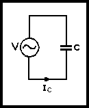
When an alternating voltage, V. is applied to a capacitor, C. (Fig 2.8) the current leads the voltage by 90º. The current which flows is given by:
![]() where XC
is the capacitive reactance,
where XC
is the capacitive reactance,
![]() ohms.
ohms.

Fig 2.8. Alternating voltage applied to Capacitor C
When an alternating voltage is applied to an inductor and a capacitor in series, the current flowing and the phase angle between the voltage and current will depend upon the effective reactance, X , of the circuit ie (X L-X C) or (X C-X L) ; thus the circuit will be inductive if XL is greater than XC or capacitive if XC is greater than XL.
If now there is a resistor, R, in series with the inductor and capacitor, the total opposition to the flow of an alternating current is known as the 'impedance', Z. This impedance is made up of resistance, R, and the effective reactance, X. Both R and X are measured in ohms, but they must not be added arithmetically. As a result of the 90o phase shift introduced by the inductance and capacitance, they must be added vectorially,
ie by taking the square root of the sum of the squares of R and X, hence:
![]()
Ohm's Law can now be applied and so the current flowing is:
![]()
The following relationships should be noted:
Capacitors in series:
![]()
Capacitors in parallel:
![]()
Inductors in series:
![]()
Mutual inductance (which will be discussed later) is assumed to be zero.