If a bar magnet is plunged into a solenoid, as indicated in Fig 2.9(a). the moving coil microammeter connected across the coil shows a deflection. The explanation of this phenomenon, known as 'electromagnetic induction', is that the movement of the magnet's lines of force past the turns of the coil causes a voltage to be induced in the coil which in turn causes a current to flow through the meter. The magnitude of the effect depends on the strength and speed of movement of the magnet and the size of the coil. Withdrawal of the magnet causes a reversal of the current. No current flows unless the lines of force are moving relative to the coil. The same effect is obtained if a coil of wire is arranged to move relative to a fixed magnetic field. Dynamos and generators depend for their operation on the principle of electromagnetic induction.
Suppose a pair of coils of wire is arranged as shown in Fig 2.9(b). When the switch K is open there is no magnetic field from the coil P linking the turns of the coil S, and the current through S is zero. Closing K causes a current in the coil P which produces a magnetic field. This field, as it builds up from zero, induces a voltage in S and causes a current to flow through the meter for a short time until the field due to P has reached a steady value, when the current through S falls to zero again. The effect is only momentary and is completed in a fraction of a second. The change in current in the circuit P is said to have 'induced' a voltage in the circuit S. The fact that a changing current in one circuit can induce a voltage in another circuit is the principle underlying the operation of transformers.

Fig 2.9. Electromagnetic induction. (a) Relative movement of magnet and coil causes a voltage to be induced in coil; (b) when current In one of a pair of coupled coils changes in value, a voltage is induced in the second coil.

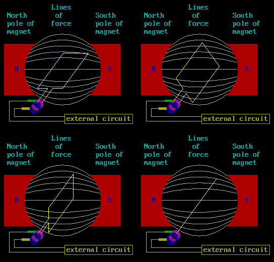
Diagram 2.3 A dynamo in action.
The action of the coil (yellow) cutting the magnetic field, causes current and voltage to be generated between the terminals. The static carbon brushes (yellow and green) allow the current to be 'picked' up from the rotating contacts of the rotating coil. The switching action at this point, ensures DC is generated. If the connection is not switched during the rotation, then AC will be generated. There is basically little difference between the design of a small DC motor, and a small DC generator (dynamo).
If a steady current is flowing through a coil, there is a steady magnetic field due to that current. A current change tends to alter the strength of the field, which in turn induces in the coil a voltage (back EMF) tending to oppose the change being made. A negative sign is generally used before a back EMF to indicate that it is contrary to the supply voltage. This process is called 'self-induction'. A coil is said to have 'self-inductance', usually abbreviated to 'inductance', It has a value of one 'henry' (H) if, when the current through the coil changes at a rate of 1A/s(1 ampere per second). the voltage appearing across its terminals is 1V. Inductance is usually denoted by the symbol L in formulae. As the inductance values used in radio equipment may be only a fraction of a henry, the units 'millihenry' (mH) and 'microhenry' (μH) (0.001 and 0.000001H respectively) are commonly used.
The inductance of a coil varies as the square of the number of turns, the cross-sectional area, and the permeability of the core, and inversely as the length of the magnetic path.
![]()
A changing current in one circuit can induce a voltage in a second circuit (see Fig 2.9(b)). The strength of the voltage induced in the second circuit S depends on the closeness or 'tightness' of the magnetic coupling between the circuits; for example, if both coils are wound together on an iron core, practically all the lines of force or magnetic flux from the first circuit link with the turns of the second circuit. Such coils are said to be 'tightly coupled' whereas if the coils are both air-cored and spaced some distance apart they are 'loosely coupled'.
The mutual inductance between two coils is measured in henrys, and two coils are said to have a 'mutual inductance' of 1H if when the current in the primary coil changes at a rate of 1A/sthe voltage across the secondary is 1V. Mutual inductance is denoted in formulae by the symbol M.
The mutual inductance between two coils may be measured by joining the coils in series, first so that the sense of their windings is the same, and then so that they are reversed. The total inductance is then measured in each case.
If La and Lb are the total measured inductances, L1 and L2 are the separate inductances of the two coils and M is the mutual inductance, then:

![]()
![]()
The mutual inductance is therefore equal to one quarter of the difference between the series-aiding and series-opposing readings.