Any of the many different oscillator circuits may be used as the VFO, but the generally used circuits are the Colpitts or the Clapp-Gouriet. The factor of prime importance in the design of the VFO is its frequency stability, because:
Frequency stability is particularly important in a transmitter intended for single sideband operation.
The frequency of an oscillator is determined by the resonant frequency of its tuned circuit, thus
![]()
Therefore the magnitude of L, the inductance of the coil, and of C , the capacitance necessary to tune L to the required frequency should not vary under any circumstances.
The factors which may cause L and C to vary are:
Preferably the coil should be air-cored as any form of dust-iron core will cause an additional variation of the inductance of the coil with temperature. The effect of temperature on the tuned circuit may be minimised by locating it as far as possible from any source of heat.

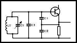
Fig 4.5. Connection between tuned circuit (LT CT) and transistor in Colpitts-type oscillator
In the Colpitts and similar oscillators, the effect of change in transistor capacitances is minimised by the particular circuit configuration (see Fig 4.5). C1 and C2 are large and swamp the transistor capacitances, but they are part of the frequency-determining capacitance, and so their change in value with temperature is important. These capacitors should be of good quality, preferably having mica or polystyrene as the dielectric. These will have a small positive temperature coefficient which may be compensated for by the experimental addition of a low-value ceramic dielectric capacitor which has a large negative temperature coefficient (C3 in Fig 4.5).
To summarise, the tuned circuit of a VFO must be soundly made and use best-quality components.
The VFO should be considered as a source of a small output voltage at a constant frequency. It should not be close to any source of heat. The VFO should be lightly loaded by the following stage; excess loading may ultimately stop the oscillation, and any change in loading, if heavy (eg during keying), may well cause a change in frequency ('chirp'). The VFO should ideally be followed by an isolating stage such as a Class A buffer amplifier.
Variation of supply voltage can cause a change in transistor parameters and hence in frequency. Thus stabilisation of the supply voltage is advisable. This is normally achieved by the use of a zener diode (see Chapter 6).

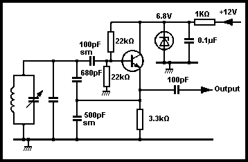
Fig 4.6. Typical Colpitts type oscillator circuit
For frequency-stability reasons, it is considered inadvisable to key a VFO: furthermore it should operate at the lowest possible frequency. This is because the effects of the likely sources of frequency drift increase as the frequency increases. It should be noted that some frequency drift is inevitable during the first few minutes of operation after switch on from cold; it is the drift after this period which must be reduced to the minimum. Fig 4.6 is the circuit diagram of a Colpitts VFO.
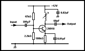
Frequency multipliers are normally low-power transistors operating in Class C in order to produce a collector current which is rich in harmonics. The circuit of such a stage is shown in Fig 4.7.

Fig 4.7. Basic circuit of a frequency multiplier
The tuned circuit is resonant at n x f, where f is the frequency of the input voltage and n is usually 2 or 3. Higher multiplications may be used but the output is rather low. The tuned circuit may consist of a small coil and variable capacitor or a slug tuned coil and fixed capacitor.
Synthesisers are notoriously difficult to design and build with a low spurious output level. The design of the phase comparator and loop filter is very critical because any noise or AC components will modulate the VCO and produce unwanted sidebands on the output frequency. These can give rise to considerable interference on transmit. Also there is the possibility of the system going 'out of lock'. This may mean that the VCO could wander completely out of control up and down the band.
A stable frequency source followed by a multiplier chain is a convenient arrangement for the VHF (70 and 144MHz) and UHF (430MHz) bands as the transmitters used at these frequencies are generally single-band transmitters. Due to the increased circuit losses at the higher frequencies, a buffer amplifier may be necessary before the output stage.

Fig 4.8. Block diagram of a 144MHz transmitter
For stability reasons, crystal oscillators (frequencies in the region of 6MHz, 8MHz or sometimes 12MHz) can be used, but phase-locked loops are usual. A block diagram of an exciter for 144MHz is shown in Fig 4.8.
It will be seen that the addition of a further tripler stage will give an output at 432MHz and that with a slightly different crystal frequency, the first two multiplying stages will provide an output at 70MHz.