![[Picture]](../gfx/dwg/f5-13.gif)
The frequency stability of the transmitter and receiver are especially important in an SSB communication system. The carrier re-insertion process also must be done accurately. Unless the local signal is within 25Hz of the original (suppressed) carrier frequency there will be distortion, and if the frequencies differ by much more than that figure, the SSB transmission will be unreadable.
A narrow band filter (2.5-3kHz) is required to remove one sideband in the transmitter and a similar filter is advantageous in the receiver. Both require a very stable VFO.
For these reasons, the transmitter and receiver circuits can be combined to produce the 'transceiver' in which the same VFO and filter are used in both the transmit and receive functions. This is now the preferred arrangement for SSB operation; it can also be used for telegraphy.
The modern transceiver is compact and inevitably complex in design. It is often followed by a separate linear amplifier to boost the power to the legal maximum. Fig 5.13 is a block diagram of a typical transceiver.
Fig 5.13. Block diagram of SSB transceiver (from A Guide to Amateur Radio)
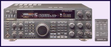
Kenwood TS950, a modern HF transceiver. This unit contains the transmitter and receiver for the HF (10kHz-30MHz) bands. This unit is very sophisticated and even has an (optional) remote control ! Before units such as these arrived on the market, separate transmitter and receiver units such as the combination pictured below, a Yeasu FLDX400 transmitter (right) and FRDX400 receiver (left), were more commonly used.
![[yeasu f-line]](../gfx/photos/yaesu_fline.jpg)